I can't find a wiring diagram...
Moderator: bclaire
I can't find a wiring diagram...
For a FS-2 footswitch. I have a two button switch and want to wire it for my cr120. I can get the switching to work but the LEDs work opposite of the way they should. Can anyone help? Thanks.
Re: I can't find a wiring diagram...
Here's the basic schematic for each footswitch inside the FS 2 (it's just 2 of these in a single housing):
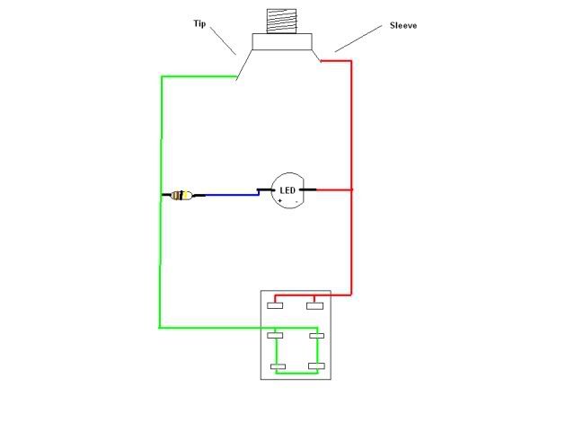
( stock FS's (1's anyway) come with a 470 ohm resistor I believe.)
Sounds like you just need to wire the LEDs to the other side of the switches. That way they'll light up when the channel is on rather than off. Are the switches 3PDT? If the schematic above doesn't do it for you, can you take a picture of the inside of the footswitch?
RV 50 MKI | TH30 | RV 50 MKIII
G&L Tele (ASAT Classic) | Musicman Bongo 5
Anesthesia - Post-Rock/Ambient band - anesthesiaproject.com
G&L Tele (ASAT Classic) | Musicman Bongo 5
Anesthesia - Post-Rock/Ambient band - anesthesiaproject.com
Re: I can't find a wiring diagram...
Thank you very much. I have a SPDT I believe. It has three posts. Would it work the same way? I can take a pic but I'm sure the center post switches to either of the outside posts when stomped. Thanks again and please let me know if my setup will work. I'm thinking the diagram is the way I thought I did it.
Re: I can't find a wiring diagram...
If you have 3 posts, then you at least have a DP...you might just not have double throws, which is fine. Sounds like maybe you have a DPST, but either way, as long as you have 3 poles you're golden. (EDIT: I've been doing true bypass strips too much lately and kept tying 3PDT instead of DPDT, dang it.)
I actually made two of these a few years ago to downsize my FS to fit on my board and after taking them apart yesterday to try to help you, I realized I wired them completely backwards from the stock footswitches and the schematic I posted before, but they work perfectly...which makes sense.
I'm still not exactly sure how the LEDs are lighting up when you're on the clean channel and when the reverb is off...that is what is happening correct? You just said they're not working the way they should...so I'm just making sure we're both expecting the same behavior. Can you confirm currently this is what is happening:
Clean = LED ON | Verb off = LED ON
Dirty = LED OFF | Verb on = LED OFF
I've heard of the channel switching working, but the LED not lighting (usually an issue of the LED being wired backwards) but I've never heard of them lighting opposite of how they should. The switch is the only thing I can think of.
I'm trying to wire up my own again to see if I can configure it to replicate when you're experiencing...I'll let you know if I do.
Let me know what you find!
Last edited by Phlowen on Sat Jun 28, 2014 1:34 am, edited 1 time in total.
RV 50 MKI | TH30 | RV 50 MKIII
G&L Tele (ASAT Classic) | Musicman Bongo 5
Anesthesia - Post-Rock/Ambient band - anesthesiaproject.com
G&L Tele (ASAT Classic) | Musicman Bongo 5
Anesthesia - Post-Rock/Ambient band - anesthesiaproject.com
Re: I can't find a wiring diagram...
Yep, that's what it was doing. I thought I had I just like your diagram only with three posts instead of six. I'll swap + & - on the led to see if maybe it is backwards. I'll let you know. Thanks.
Re: I can't find a wiring diagram...
Wiring the LED to the other side of the switch won't work. You'd need to reverse the NC and NO wiring on the relays inside the amp.

Re: I can't find a wiring diagram...
And the LED wouldn't light up at all if it was wired backwards. Switching the + and - at this point will most likely ensure that it won't light up at all.
Jondog - what you offered makes perfect sense, but couldn't he just swap the tip and sleeve connections (and flip the LED polarity so that it still works) in the pedal to reverse those relays' polarities? It would seem odd that Orange would wire this 1 amp backwards from the rest such that it wouldn't even work correctly with their own stock FS 2. That is, unless someone reversed the relays from stock before you bought it ChrisinMO...are you the original owner?
Also, if you have to reverse the polarities of the relays in the amp, it's probably safer to just use a different foot switch...
But again, if you wired yours correctly to match the stock FS, then using a similar footswitch won't lead to different results...
RV 50 MKI | TH30 | RV 50 MKIII
G&L Tele (ASAT Classic) | Musicman Bongo 5
Anesthesia - Post-Rock/Ambient band - anesthesiaproject.com
G&L Tele (ASAT Classic) | Musicman Bongo 5
Anesthesia - Post-Rock/Ambient band - anesthesiaproject.com
Re: I can't find a wiring diagram...
I don't think so. I was trying to figure this out once before. Switching the tip and sleeve connections and the LED would basically just give you the same thing. All the switch does is turn on and off the voltage to the relay coils, which is a completely different circuit from the actual audio signal path through the relays. This same voltage lights the LED. So when the relays are activated, the LED lights up because the voltage circuit is completed through the relay coil network. No one could switch the relay wiring without some serious modding to the PCB. A simple fix is to have a footswitch with a battery powered LED.Phlowen wrote:And the LED wouldn't light up at all if it was wired backwards. Switching the + and - at this point will most likely ensure that it won't light up at all.
Jondog - what you offered makes perfect sense, but couldn't he just swap the tip and sleeve connections (and flip the LED polarity so that it still works) in the pedal to reverse those relays' polarities? It would seem odd that Orange would wire this 1 amp backwards from the rest such that it wouldn't even work correctly with their own stock FS 2. That is, unless someone reversed the relays from stock before you bought it ChrisinMO...are you the original owner?
Also, if you have to reverse the polarities of the relays in the amp, it's probably safer to just use a different foot switch...
But again, if you wired yours correctly to match the stock FS, then using a similar footswitch won't lead to different results...
Re: I can't find a wiring diagram...
Yeah but again if it's the relays then even Orange's footswitches wouldn't work for this amp, which doesn't make sense...it can't be that complicated of a fix.Jondog wrote: I don't think so. I was trying to figure this out once before. Switching the tip and sleeve connections and the LED would basically just give you the same thing. All the switch does is turn on and off the voltage to the relay coils, which is a completely different circuit from the actual audio signal path through the relays. This same voltage lights the LED. So when the relays are activated, the LED lights up because the voltage circuit is completed through the relay coil network. No one could switch the relay wiring without some serious modding to the PCB. A simple fix is to have a footswitch with a battery powered LED.
I thought the LED lit up because the switch cuts the direct tip to sleeve connection (path of least resistance) leaving only the resistor and LED to complete the circuit. Otherwise, the current passes over the resistor and LED in favor of the direct connection (actually I'm certain at least this part is how it's working because when the LED is lit, the switch is connected to the side that simply connects the tip back to itself again breaking the circuit, forcing current down the LED + resistor line, I checked with my meter). Then I assume the relays open and closed based on the current changing (EDITED: I originally said "voltage" changing by mistake). BUT, it's been a long time since I worked with relays and I could be 100% wrong about that.
So basically, the LED+Resistor has to be wired parallel to the switch and before it. All the switch does is short out the LED+Resistor by completing the circuit directly (first pole) OR by breaking the switch out of the circuit, thereby leaving the LED+Resistor as the only completion of the circuit, forcing current through them (2nd pole). This still doesn't explain how he's getting channel switching as expected, but LEDs lighting opposite of expected. But I am certain it can be fixed in the switch, and not in the amp.
ChrisinMO...can you open up your footswitch and send a picture? That may very well be all that is needed to see the issue.
Last edited by Phlowen on Fri Jun 27, 2014 8:51 pm, edited 2 times in total.
RV 50 MKI | TH30 | RV 50 MKIII
G&L Tele (ASAT Classic) | Musicman Bongo 5
Anesthesia - Post-Rock/Ambient band - anesthesiaproject.com
G&L Tele (ASAT Classic) | Musicman Bongo 5
Anesthesia - Post-Rock/Ambient band - anesthesiaproject.com
Re: I can't find a wiring diagram...
I don't think we are on the same page. But this diagram shows what I'm talking about power wise. On the relays switches themselves you only have 2 options, normally open and normally closed. The only time the LED is going to light is when the relay coil is activated by completing the circuit and the switch goes to the normally open contacts. Whatever channel is on the normally open contacts will decide what channel the LED lights up on. It also depends alot on how the channels are wired into the relays as well and if they are DPDT or SPDT etc.. etc.. On amps like the AD30 and Rocker 30, the relays NO and NC terminals ground one channel out rather than pass the audio signal through.

Re: I can't find a wiring diagram...
Here's my understanding of this
The channel switching relays use a DC supply.
The relays have two states:
On - which is when sufficient current is flowing through the relays' coils to make them switch to position 2.
Off - which is when insufficient current is being supplied to the coils, and they stay in position 1.
The front channel changing switch just switches the current on (or off) to the relays' coils.
The 'footswitch' jack is of a switching type, such that when a jack is inserted, the relay DC supply circuit is diverted out to to the footswitch itself. Thus 'making' the switch completes the circuit and energises the relay coils, switching the channels - and 'breaking' the switch does the opposite.
With a pedal like the FS-1 things get a bit more interesting.
The LED can only be lit when the footswitch is 'breaking' - the relay current is diverted through the led in series with the resistor.
When in this situation current flows from the DC relay supply out to the footswitch, through the LED and resistor, and then back through the relay coils themselves. Yes, that's right, there is current flowing through the relay coils - BUT this current is limited by the LED/resistor hence it isn't enough current to actually close the relay.
When the footswitch is 'making' the led and resistor get shorted out (so the LED doesn't light) and all the current gets to flow through the relay control coils, so they switch.
I can't imagine any way you could get sufficient current flowing through the coils to make them switch and at the same time get current flowing through the LED/resistor. Small relays need around 40mA to switch, LEDs can typically handle 20mA.
I think you wire the led in series with the switch without a resistor the LED will get too much current through it and will blow.
Cheers
Jon
Re: I can't find a wiring diagram...
That diagram isn't consistent with the situation we're in. If you look at the schematic for the Orange footswitch, you can see that it's always a completed circuit...the LED + Resistor directly connecting the tip to sleeve shows that. The switch wired in parallel simply serves as a way to short circuit the LED+Resistor. The diagram you showed doesn't quite work the same way as it expects either an open or closed circuit. The orange circuits are always closed, but the relays are activated by the decreased or increased flow of current made possible by the voltage drop or lack thereof as instigated by the footswitch.
When the footswitch closes (connects the tip to the sleeve unimpeded) there's no change in voltage, therefore there is no current flowing in the footswitch, but current is flowing fully in the relays, the amp is on clean and the LED is off (at least this is the normal, expected behavior). When the footswitch opens (connects the Tip to nothing or back to itself) suddenly the LED + Resistor connecting the Tip to Sleeve in front of the switch has a voltage drop, which means current, diverted from the relays flows through the footswitch, which means the LEDs come on, and the relays switch (reacting to the decreased current).
And regardless of everything I just said...if we're duplicating the Orange Foot switch, we don't really need to worry about how the relays in the amp work because we know the Orange Foot Switch works with the amp, right?
Therefore, with ChrisinMO's set up, it has to be an issue with his footswitches, not the relays in his amp.
Last edited by Phlowen on Fri Jun 27, 2014 8:49 pm, edited 2 times in total.
RV 50 MKI | TH30 | RV 50 MKIII
G&L Tele (ASAT Classic) | Musicman Bongo 5
Anesthesia - Post-Rock/Ambient band - anesthesiaproject.com
G&L Tele (ASAT Classic) | Musicman Bongo 5
Anesthesia - Post-Rock/Ambient band - anesthesiaproject.com
Re: I can't find a wiring diagram...
YES JON! You've got it!
For some reason I didn't see your reply before I posted mine directly above this one. You explained it far better than I.
For some reason I didn't see your reply before I posted mine directly above this one. You explained it far better than I.
Exactly! It's baffling me!jontheid wrote: I can't imagine any way you could get sufficient current flowing through the coils to make them switch and at the same time get current flowing through the LED/resistor. Small relays need around 40mA to switch, LEDs can typically handle 20mA.
RV 50 MKI | TH30 | RV 50 MKIII
G&L Tele (ASAT Classic) | Musicman Bongo 5
Anesthesia - Post-Rock/Ambient band - anesthesiaproject.com
G&L Tele (ASAT Classic) | Musicman Bongo 5
Anesthesia - Post-Rock/Ambient band - anesthesiaproject.com
-
Randy Bass
- Lord of Orange
- Posts: 10149
- Joined: Tue Sep 29, 2009 3:44 am
Re: I can't find a wiring diagram...
The Orange footswitch LED has always worked backwards on the Crush amps and correctly on valve models. Doesn't that mean the difference is in the relay circuitry of the Crush models? It seems like you'd have to modify the amp to resolve that unless you power the footswitch LED with a battery.
_________________

Re: I can't find a wiring diagram...
YesDoesn't that mean the difference is in the relay circuitry of the Crush models?
Who is online
Users browsing this forum: Google [Bot] and 30 guests