Had the day off, I got bored so I did this. This is just the Natural Channel into the Phase inverter. Didn't have time to do the Dirty. I also did the power amp but I haven't drawn it on the PC yet. Also not guaranteeing it's 100% accurate, so if you see something wrong, feel free to correct me!
'photo deleted and updated later in topic'
Rocker 30 circuit
Moderator: bclaire
Re: Rocker 30 circuit
'photo deleted and updated later in topic'
Last edited by Jondog on Mon Feb 18, 2013 2:37 pm, edited 4 times in total.

-
fiveightandten
- Orange Master
- Posts: 3845
- Joined: Sat Apr 05, 2003 6:18 pm
- Location: Connecticut, USA
Re: Rocker 30 circuit
Very cool. Thanks for posting! 
-Nick
-Nick

'71 GRO100 || '96 OR-80 || AD30 || '64 AC-50 || AC-30TBX || Hiwatt DR504 || HI-TONE HT30
LP Standard || LP Studio || LP Custom Lite || Ric 620 || Ric 360 || MIA Tele || SG 61 RI
-
a.hun
- Duke of Orange
- Posts: 9765
- Joined: Sat Jun 15, 2002 1:05 am
- Location: Amsterdam, Hollandland.nl
Re: Rocker 30 circuit
+1fiveightandten wrote:Very cool. Thanks for posting!
-Nick
Andy.
aNDyH. 
Ever tried to outstare a mirror?
In the bathtub of history the truth is harder to hold than the soap, and much more difficult to find!
Ever tried to outstare a mirror?
In the bathtub of history the truth is harder to hold than the soap, and much more difficult to find!
Re: Rocker 30 circuit
'photo deleted and updated later in topic'
Not shown but R45 runs parallel with R46 from the Natural channel schematic into C25 to the P.I. Thought I should mention.
Not shown but R45 runs parallel with R46 from the Natural channel schematic into C25 to the P.I. Thought I should mention.
Last edited by Jondog on Mon Feb 18, 2013 2:36 pm, edited 5 times in total.
Re: Rocker 30 circuit
Thank you! I can FINALLY sleep at night now. Whew.

-Electrical Guitar Company "Buzzo" Double-Cut, Solid Aluminum, Gold Anodized.
-Gronlund Newcomb Custom aluminum hollow-body guitar.
-Matchless Phoenix 35 w/ Matchless 4x10 Cabinet
Re: Rocker 30 circuit
If you happened to have copied these or printed them before today, take another look as I've updated some of the resistor values. Have trouble with brown and red colors sometimes! I've also done the power supply section, but haven't drawn it up neatly yet. Struggling a bit with the relay switching though, does some weird things which is difficult to trace and I'm not that experienced.
Re: Rocker 30 circuit
Hi everyone,
this is my first post on this board.
Looking at the schem, some things are weird:
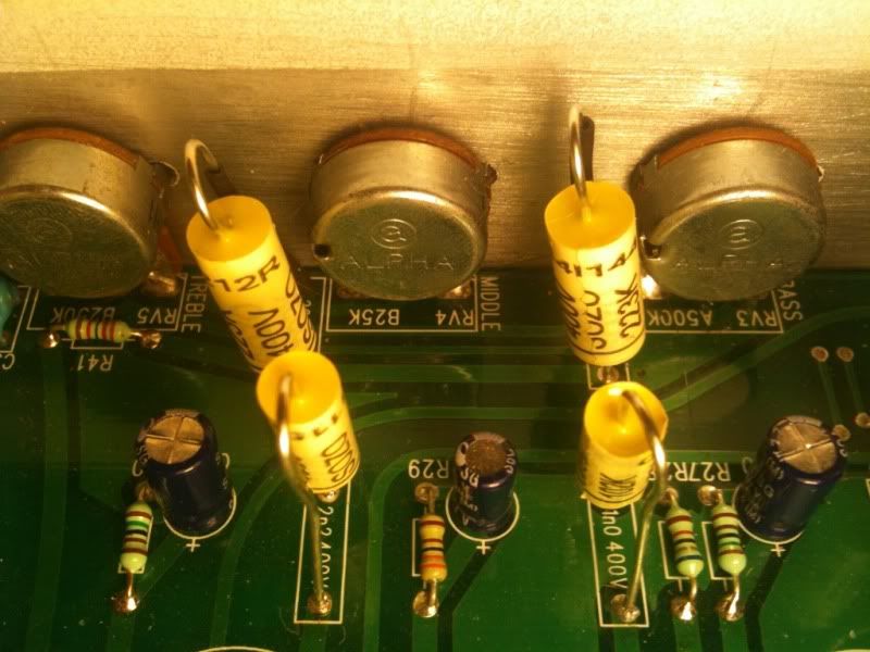
- R41 (slope reistor) can't be 1.1k, it should be much higher.
- RV5 I would expect 250k for Treble.
- RV4 is Bass and RV3 is Mid, also exchange the values.
Cheers,
Kell
this is my first post on this board.
Looking at the schem, some things are weird:
- R41 (slope reistor) can't be 1.1k, it should be much higher.
- RV5 I would expect 250k for Treble.
- RV4 is Bass and RV3 is Mid, also exchange the values.
Cheers,
Kell
Re: Rocker 30 circuit
Hi, welcome and thanks. Must of made a typo on the treble pot, supposed to be 250k like you say. Good eye with r41, should be 22k, that would be my red/brown trouble kicking in!. But rv3 bass and rv4 mid are the correct positions for bass and mid.kell wrote:Hi everyone,
this is my first post on this board.
Looking at the schem, some things are weird:
- R41 (slope reistor) can't be 1.1k, it should be much higher.
- RV5 I would expect 250k for Treble.
- RV4 is Bass and RV3 is Mid, also exchange the values.
Cheers,
Kell
Re: Rocker 30 circuit
Sorry,
but the pot in the middle wired as shunt is a bass control. The other one below with its wiper connected to C31 is the mid control. So it should read:
RV4: Bass – 500kΩ
RV5: Mid – 25KΩ
Cheers,
Kell
but the pot in the middle wired as shunt is a bass control. The other one below with its wiper connected to C31 is the mid control. So it should read:
RV4: Bass – 500kΩ
RV5: Mid – 25KΩ
Cheers,
Kell
Re: Rocker 30 circuit
kell wrote:Sorry,
but the pot in the middle wired as shunt is a bass control. The other one below with its wiper connected to C31 is the mid control. So it should read:
RV4: Bass – 500kΩ
RV5: Mid – 25KΩ
Cheers,
Kell
I think where the confusion is, is that Ive labelled it wrong. Rv4 25k mid should be the bottom one, rv3 500k the middle.
Last edited by Jondog on Sun Feb 17, 2013 9:15 pm, edited 1 time in total.
Re: Rocker 30 circuit
RV3: Bass – 500kΩ
RV4: Mid – 25KΩ
The labels in your schematics should be corrected, too.
Cheeers
RV4: Mid – 25KΩ
The labels in your schematics should be corrected, too.
Cheeers
Re: Rocker 30 circuit
Will do! Glad you took notice!kell wrote:RV3: Bass – 500kΩ
RV4: Mid – 25KΩ
The labels in your schematics should be corrected, too.
Cheeers
Re: Rocker 30 circuit
Do you plan to mod something, or is this just for reference?
Re: Rocker 30 circuit
I've done a couple mods to my Rocker before I did this and wished I had schematics. More less reference I guess. You can get schematics for many Oranges but the Rocker isn't one thats readily available on the net and Orange won't give them out. I've asked and so have many others! I don't know why, many amp companies include them in the manuals. I just decided to try and sort it out, maybe a help to others. Tracing the circuits for each preamp and the poweramp wasn't too hard, alot of back and forth. Looking at other Orange schematics helped a bit too as there are some similarities. The Rocker is it's own beast though, unlike the newer Oranges which all seem to copy preamps (mainly the Rockerverb), tonestacks and poweramps and do mix and matches to create a new model, even use the same PCB. I don't know of another Orange like the Rocker internally. Do you know much about relays? Having a bit of trouble with those for the channel switching. Have a rough idea of how it's wired but not sure as it's not like the AD series or the Rockerverb. I know it grounds one channel out, while the other is engaged and I think Relay 1 is after the Dirty gain pot, rather then before the input resistor on the dirty channel as I've labeled it. Also, if you know about the negative feed have a look at what I have labeled as that. Nothing states thats what it is, but according to the Rockerverb schematic, thats what it looks like.kell wrote:Do you plan to mod something, or is this just for reference?
Last edited by Jondog on Sun Feb 17, 2013 9:52 pm, edited 1 time in total.
Who is online
Users browsing this forum: No registered users and 151 guests