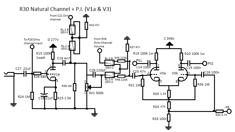
Thats where I'm getting confused. The Rockerverb uses SPST relays. But if I were to do a re-build it would probably work with that method I suppose. As for the grid leak, I didn't put it in the schematic, guess I should. The two channels share R24 and it grounds out to the cathode capacitor ground on the Natural channelkell wrote:Hi,
I think there is more than one mistake.
Have a look at this schem.
http://www.orangefieldguide.com/OFG_SCH ... sheet1.jpg" onclick="window.open(this.href);return false;
... wouldn't be surprised if yours is similar to this – of course pure guesswork.
I also noticed, there is no grid leak resistor before R28 to ground (dirty channel). Did you forget it, or do both channels share the same? (Clean channel has R24/1M e.g.)

Cheers
Rocker 30 circuit
Moderator: bclaire
Re: Rocker 30 circuit

Re: Rocker 30 circuit
Jondog,
your switching logic needs a second view with eagle eyes!
The longer I look at it, the less it makes sense. Please check it again.
Cheers
your switching logic needs a second view with eagle eyes!
The longer I look at it, the less it makes sense. Please check it again.
Cheers
Re: Rocker 30 circuit
Pretty sure I've got it sorted out now. Took a break and came back at it from a different angle. I was basically looking at it backwards and it was confusing me. Took me about a minute to figure it out with a new point of view. Been spending too much time with it!kell wrote:Jondog,
your switching logic needs a second view with eagle eyes!
The longer I look at it, the less it makes sense. Please check it again.
Cheers
Re: Rocker 30 circuit
... sounds familiar to me. 
Cheers
Cheers
Re: Rocker 30 circuit
Makes sense to me anyways, even if it's not right.
Last edited by Jondog on Wed Feb 20, 2013 7:45 pm, edited 2 times in total.
Re: Rocker 30 circuit
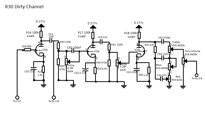
Makes sense to me, except I can't find a cap labelled C21 on the dirty channel schematic - is it the 1st interstage coupling cap?
Excellent work by the way, I've wanted to know what is in the heart of the Rocker for years.
Excellent work by the way, I've wanted to know what is in the heart of the Rocker for years.
Re: Rocker 30 circuit
Yes, I just noticed on the schematic I uploaded I didn't label the capacitor number, but it's the 1n0 cap before R44. Thanks for the compliment. I got tired of waiting for it to show up somewhere, so I made it show up.jontheid wrote:Makes sense to me, except I can't find a cap labelled C21 on the dirty channel schematic - is it the 1st interstage coupling cap?
Excellent work by the way, I've wanted to know what is in the heart of the Rocker for years.
Re: Rocker 30 circuit
I'm sure Gladmarr would be more than happy to host the schematics on the Orange Amp Field guide when completed.
Re: Rocker 30 circuit
Great work! 
I noticed R39 on the Natural Channel, 140Ω is much too low.
Suggestion : If R26/68k is made much smaller there will also be less noise, as this one is in series and the first gain stage is maxed out for gain. Especially the Dirt Channel benefits from this (less noise and hiss). If RF occurs a liitle cap can be soldered directly from grid to ground as a shunt.
I noticed R39 on the Natural Channel, 140Ω is much too low.
Suggestion
Re: Rocker 30 circuit
I've been questioning that resistor R39 since I first did it. The bands are really close together and they are 5 band resistors, each end has a brown band as they all do (1% tolerance) and couldn't tell which end was which. Does a 1M seem like it would work in your opinion? That's the value reading it the other way around.kell wrote:Great work!
I noticed R39 on the Natural Channel, 140Ω is much too low.
Suggestion
Re: Rocker 30 circuit
Which colours can be seen? Brown on both ends, one is yellow and the other two?
Of course 1M could make sense...
Of course 1M could make sense...
Re: Rocker 30 circuit
Black,Blackkell wrote:Which colours can be seen? Brown on both ends, one is yellow and the other two?
Of course 1M could make sense...
Re: Rocker 30 circuit
Definitley 1MΩ. 
Re: Rocker 30 circuit
This has me intrigued. I'm late to the party, but that's nothing new.

Who is online
Users browsing this forum: No registered users and 145 guests