Re: OR120 mod
Posted: Sun Nov 10, 2019 7:06 pm
Old thread but well worth the discussion 
Some points though.
I agree that using a 220k to ground as a voltage divider on the grids is a way of attenuating signal and it was not used on the early Matamps, or the OR series of Orange/Matamps it was used on the Matamp GT100 in the early 70s (which also sported a 470k to ground after the wiper of the volume control and before the grid of V1b). Of course the early tagboard ORSTs had a 1meg pot in series with a 22k to ground (albeit the pot bypassed with a 5nF cap).
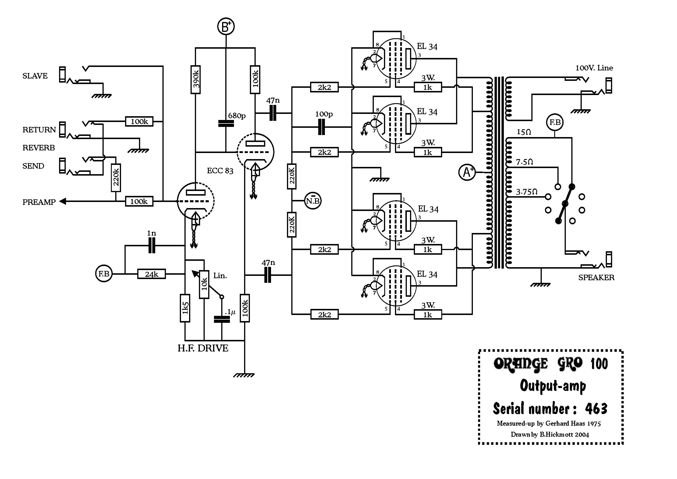
Next poin is that the Ormats and later Oranges still kept 100k anode resistors in the PI. The 390k resistor is on the anode of V2a (a 'gain' stage) and was always bypassed with a capacitor, from the early Matamp 2000 which had a 2200pF bypass cap there (and curiously an asymetric cathodyne PI as the plate resistor was 100k and the cathode resistor 82k (remedied on the ORST with 100k and 100k). The ORST used a 680pF bypass cap on the 390k and the OR100 of that era used 1nF on the lead amps and 680pF on the Bass version (at least on those that I have worked on).
Now you mention the directly coupled V2a to V2b being a feature of later amps but that is not the case, the Matamp 2000, the ORST, the OR100 and GROhttp://www.orangefieldguide.com/OFG_SCH ... output.jpg all had directly coupled PI, as well as the Matamp GT100http://bee.mif.pg.gda.pl/ciasteczkowypo ... GT-120.jpg.
The amp that you refer to (the '72 found with pcb mounted preamp valves - referred to as Graphic Mk 11 in the schemshttp://orangefieldguide.com/OFG_SCHEM/OR120schem_72.gif) and mid-lift inductor was the exception having the 0.068uF decoupler and 1M in series to the cathode and then that half of the PI.
Which design is better is a moot point (I like the ORST/OR100 amps for their extra bit of grit and having the depth switch early in the circuit) and have no issue with removing the 220k from V1a grid but felt that I should clarify those points before they enter Orange folk lore (although I suspect that they already have!)
Some points though.
I agree that using a 220k to ground as a voltage divider on the grids is a way of attenuating signal and it was not used on the early Matamps, or the OR series of Orange/Matamps it was used on the Matamp GT100 in the early 70s (which also sported a 470k to ground after the wiper of the volume control and before the grid of V1b). Of course the early tagboard ORSTs had a 1meg pot in series with a 22k to ground (albeit the pot bypassed with a 5nF cap).
Next poin is that the Ormats and later Oranges still kept 100k anode resistors in the PI. The 390k resistor is on the anode of V2a (a 'gain' stage) and was always bypassed with a capacitor, from the early Matamp 2000 which had a 2200pF bypass cap there (and curiously an asymetric cathodyne PI as the plate resistor was 100k and the cathode resistor 82k (remedied on the ORST with 100k and 100k). The ORST used a 680pF bypass cap on the 390k and the OR100 of that era used 1nF on the lead amps and 680pF on the Bass version (at least on those that I have worked on).
Now you mention the directly coupled V2a to V2b being a feature of later amps but that is not the case, the Matamp 2000, the ORST, the OR100 and GROhttp://www.orangefieldguide.com/OFG_SCH ... output.jpg all had directly coupled PI, as well as the Matamp GT100http://bee.mif.pg.gda.pl/ciasteczkowypo ... GT-120.jpg.
The amp that you refer to (the '72 found with pcb mounted preamp valves - referred to as Graphic Mk 11 in the schemshttp://orangefieldguide.com/OFG_SCHEM/OR120schem_72.gif) and mid-lift inductor was the exception having the 0.068uF decoupler and 1M in series to the cathode and then that half of the PI.
Which design is better is a moot point (I like the ORST/OR100 amps for their extra bit of grit and having the depth switch early in the circuit) and have no issue with removing the 220k from V1a grid but felt that I should clarify those points before they enter Orange folk lore (although I suspect that they already have!)
