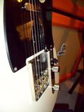
Can someone please open thier footswitch up, take a photo of the inside and post it here?
Thanks.
Orange Footswitch owners!
Moderator: bclaire
Orange Footswitch owners!
David
I'm speaking out of my a$$. Yours might differ.
I'm speaking out of my a$$. Yours might differ.
-
Donnie Osmond
- Tiny Terror
- Posts: 71
- Joined: Tue Jun 02, 2009 8:18 pm
- Location: Praxis


-
Donnie Osmond
- Tiny Terror
- Posts: 71
- Joined: Tue Jun 02, 2009 8:18 pm
- Location: Praxis
-
mr_william
- Orange Master
- Posts: 2986
- Joined: Thu Jan 18, 2007 11:25 pm
- Location: Sheffield, England
a small ammount of power comes down the jack lead to power the led..
i didnt realise it'd be a pcb.. i believe most of the others arent..
not that it makes any difference at all!..
also, why use a stereo jack socket?..surely costs would be cut using mono 1's??? even if it is only a few pence!/yuan!!
i didnt realise it'd be a pcb.. i believe most of the others arent..
not that it makes any difference at all!..
also, why use a stereo jack socket?..surely costs would be cut using mono 1's??? even if it is only a few pence!/yuan!!
Will.
Bink wrote:Will you're a genius!!
Randy Bass wrote:For the record, mr_william is a genius
-
blackcloud45
- Orange Master
- Posts: 4435
- Joined: Tue Jul 11, 2006 5:46 pm
- Location: USA
Oh man, I am pissed! All that big old huge pedal (and waste of pedal board real estate) for that? WTF? I am soooo making my own...
http://hypersoulrocks.com/index.html" onclick="window.open(this.href);return false;
http://www.myspace.com/lovea45" onclick="window.open(this.href);return false;

Thanks a bunch Donnie!!Donnie Osmond wrote:Your wish is my command......
Did you happen to take notice of what kind of resistor that is, can you read the colorcode please.
Another thing. It looks as the LED:s solderjoints are connected. Is it so or does it just look that way on the picture?
That's the whole beauty with it, and the reason I want to see how it's wired.wtf?
no battery?
BUT HOW DOES IT MAKE POWER THE LITTLE ORANGE BOULB?!?!
David
I'm speaking out of my a$$. Yours might differ.
I'm speaking out of my a$$. Yours might differ.
-
Donnie Osmond
- Tiny Terror
- Posts: 71
- Joined: Tue Jun 02, 2009 8:18 pm
- Location: Praxis
I can't tell on the LEDs solderjoints. If I had to guess, I'd say no - there is green between them - very little, but it's there. Oh yeah - here:Orphin wrote: Did you happen to take notice of what kind of resistor that is, can you read the colorcode please.
Another thing. It looks as the LED:s solderjoints are connected. Is it so or does it just look that way on the picture?


-
blackcloud45
- Orange Master
- Posts: 4435
- Joined: Tue Jul 11, 2006 5:46 pm
- Location: USA
I spoke w/ Orange USA and they advised that the cable from the head feeds ~3ma back to the pedal to operate the led. He also advised that the power is returned via the same cable (like a loop) and that this power essentially operates the switch in the amp itself causing it to complete a circuit when pressed thus switching channels.
I was asking about it because I had Analogman make me a switch and it wasn't operating properly due to not returning the required voltage. I'm noe expert, that's just what they told me for what it's worth...
I was asking about it because I had Analogman make me a switch and it wasn't operating properly due to not returning the required voltage. I'm noe expert, that's just what they told me for what it's worth...
http://hypersoulrocks.com/index.html" onclick="window.open(this.href);return false;
http://www.myspace.com/lovea45" onclick="window.open(this.href);return false;
Thanks a lot!Donnie Osmond wrote:I can't tell on the LEDs solderjoints. If I had to guess, I'd say no - there is green between them - very little, but it's there. Oh yeah - here:Orphin wrote: Did you happen to take notice of what kind of resistor that is, can you read the colorcode please.
Another thing. It looks as the LED:s solderjoints are connected. Is it so or does it just look that way on the picture?
You have been most helpful!
David
I'm speaking out of my a$$. Yours might differ.
I'm speaking out of my a$$. Yours might differ.
Yup, and that's why when Billy played at a place with low mains power (something amazingly off-spec, like 100 Volts! :O ) the amp wouldn't switch properly.
This is also how Fender is able to make the footswitches for the HotRod series. Mono cable, but two switches that control channel AND dirty channel's gain.
This is also how Fender is able to make the footswitches for the HotRod series. Mono cable, but two switches that control channel AND dirty channel's gain.

The switching is being done when + and - short circuits. When you switch back to where the LED is off, it's an open circuit.blackcloud45 wrote:I spoke w/ Orange USA and they advised that the cable from the head feeds ~3ma back to the pedal to operate the led. He also advised that the power is returned via the same cable (like a loop) and that this power essentially operates the switch in the amp itself causing it to complete a circuit when pressed thus switching channels.
I was asking about it because I had Analogman make me a switch and it wasn't operating properly due to not returning the required voltage. I'm noe expert, that's just what they told me for what it's worth...
I'm really curious on what Analogman did wrong. Did you see the circuit?
How didn't it operate properly? Did it switch OK but the LED didn't light ON and OFF?
David
I'm speaking out of my a$$. Yours might differ.
I'm speaking out of my a$$. Yours might differ.
-
blackcloud45
- Orange Master
- Posts: 4435
- Joined: Tue Jul 11, 2006 5:46 pm
- Location: USA
I had him build a box that had a switch for channel selection, a switch for reverb on / off, and a Bad Bob Boost integrated into the box. One stereo cable was used for all switching functions (rather than two guitar cables, one for each switch).
The problem was that on occassion it would do this thing when switched where it seemed like it was only getting half the signal. If I went back to the dirty channel it was weak, then if I switched a couple more times it was fine. Yes, I tried it w/ new cables. Once I started using my Orange switch it started working fine every time. The guy at Orange basically said that the stereo cable didn't have enough conductors to run both functions as it couldn't supply the right amount of voltage back to the amp.
The problem was that on occassion it would do this thing when switched where it seemed like it was only getting half the signal. If I went back to the dirty channel it was weak, then if I switched a couple more times it was fine. Yes, I tried it w/ new cables. Once I started using my Orange switch it started working fine every time. The guy at Orange basically said that the stereo cable didn't have enough conductors to run both functions as it couldn't supply the right amount of voltage back to the amp.
http://hypersoulrocks.com/index.html" onclick="window.open(this.href);return false;
http://www.myspace.com/lovea45" onclick="window.open(this.href);return false;
-
Bandeapart
- Orange Master
- Posts: 3846
- Joined: Sun Aug 19, 2007 12:18 am
- Location: Los Angeles
- Contact:
I love it, it's built like a tank. I've stomped on and murdered so many other footswitches, but this one just keeps living... and the fact that you can change the length of the cable just by attaching a different one is a plus... the other ones with the attached cable are never long enough.blackcloud45 wrote:Oh man, I am pissed! All that big old huge pedal (and waste of pedal board real estate) for that? WTF? I am soooo making my own...

Orange AD30TC, Rickenbacker 360, 52RI Tele
-
blackcloud45
- Orange Master
- Posts: 4435
- Joined: Tue Jul 11, 2006 5:46 pm
- Location: USA
What colors are those please (hard to tell in the pic)? I left my switch at the jam room...Donnie Osmond wrote:I can't tell on the LEDs solderjoints. If I had to guess, I'd say no - there is green between them - very little, but it's there. Oh yeah - here:Orphin wrote: Did you happen to take notice of what kind of resistor that is, can you read the colorcode please.
Another thing. It looks as the LED:s solderjoints are connected. Is it so or does it just look that way on the picture?
http://hypersoulrocks.com/index.html" onclick="window.open(this.href);return false;
http://www.myspace.com/lovea45" onclick="window.open(this.href);return false;
Who is online
Users browsing this forum: Google [Bot] and 389 guests